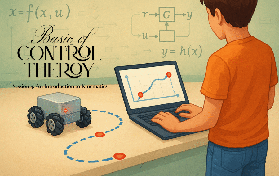
Hello and welcome back! In our last session, we assembled the “brain” of our future robot: the powerful PID controller. We learned how its three specialists—Proportional, Integral, and Derivative—work together to intelligently correct errors and command a system to meet its goal. We now have the logic to control a single motor with incredible precision.
But our robot isn’t just one motor; it’s a team of four, and they need to work together in a coordinated dance to produce useful motion. How do we translate a high-level command like “slide to the right” into the specific RPMs needed for each of the four wheels?
To answer that, we need to move from the abstract world of control algorithms to the physical world of motion. We need to understand the robot’s body. Today, we’re diving into the fascinating field of kinematics—the geometry of motion that will serve as the rulebook for our machine. 1
The Magic of Mecanum Wheels
Before we can write the rules, we need to understand the players. Our robot won’t use normal wheels. It will use special mecanum wheels. At first glance, they look like regular wheels, but they have a unique feature: small rollers mounted at a 45-degree angle around their circumference. 2
This 45-degree angle is the secret to their magic. When a normal wheel spins, it creates a force that pushes the robot directly forward or backward. But when a mecanum wheel spins, the angled rollers cause the force to be exerted at a 45-degree angle to the wheel’s direction of rotation. 4
By itself, this diagonal force isn’t very useful. But when you have four of these wheels working as a team, you can combine their diagonal force vectors in clever ways to make the robot glide in any direction.
To make this work, we need two “left-handed” and two “right-handed” wheels, arranged in an “X” pattern on the chassis. When viewed from the top, the rollers on all four wheels should point toward the center of the robot. 2
Deconstructing Motion: A Team Effort
Let’s see how this team of four wheels can create different movements by canceling out unwanted forces and combining the ones they need.
- Moving Forward: To move forward, all four wheels spin in the “forward” direction. Look at the force vectors. The sideways components of the front wheels cancel each other out, and the same happens for the back wheels. All that’s left is four force vectors pushing the robot straight ahead. 2
- Strafing (Sliding) Right: This is where it gets interesting. To slide directly to the right without turning, the wheels on the left side spin towards each other (front-left backward, back-left forward) and the wheels on the right side spin away from each other (front-right forward, back-right backward). Now, the forward and backward force vectors all cancel out, leaving only four force vectors pushing the robot perfectly to the right. 2
- Rotating Clockwise: To spin in place, the wheels on the left side spin forward, and the wheels on the right side spin backward. This time, all the forward/backward and left/right forces cancel each other out, creating a pure turning motion, or torque. 4
By combining these basic movements, a mecanum robot can move in any direction and orientation simultaneously.
Inverse Kinematics: The Control Rulebook
This is amazing, but how do we tell the wheels what to do? We need a set of equations that can take a desired robot motion and translate it into four individual wheel speeds. This process is called inverse kinematics. 1
Think of it this way:
- Forward Kinematics asks: “If I know the speed of all four wheels, what direction is the robot moving?” This is useful for tracking the robot’s position over time (a process called odometry). 1
- Inverse Kinematics asks: “If I want the robot to move forward at 1 m/s and rotate clockwise at 10 degrees/sec, what speed should I set for each of the four wheels?” This is exactly what we need to control our robot. 1
Luckily, the math for this is surprisingly straightforward. We can represent any desired 2D movement as a combination of three values:
- vy: Our desired forward/backward speed.
- vx: Our desired sideways (strafing) speed.
- ωz: Our desired rotational (turning) speed.
The inverse kinematics equations that convert these three desired motions into four wheel speeds (ωfl,ωfr,ωbl,ωbr) look like this: 4
\(\begin{align*}
\omega_{fl} &= v_y + v_x + \omega_z \\
\omega_{fr} &= v_y - v_x - \omega_z \\
\omega_{bl} &= v_y - v_x + \omega_z \\
\omega_{br} &= v_y + v_x - \omega_z
\end{align*}
\)
(Note: These are simplified equations. The true equations also involve the wheel radius and the distance from the center of the robot to the wheels, but for understanding the logic, this simplified model is perfect.) 3
Let’s test them!
- Forward Only: Set vy=1, and vx=0,ωz=0. The equations become: ωfl=1,ωfr=1,ωbl=1,ωbr=1. All wheels spin forward at the same speed. Perfect.
- Strafe Right Only: Set vx=−1, and vy=0,ωz=0. The equations become: ωfl=−1,ωfr=1,ωbl=1,ωbr=−1. This matches the pattern we described for strafing. Perfect.
- Rotate Counter-Clockwise Only: Set ωz=1, and vy=0,vx=0. The equations become: ωfl=1,ωfr=−1,ωbl=1,ωbr=−1. The left wheels spin forward and the right wheels spin backward. Perfect.
These four simple equations are our robot’s rulebook. They are the critical link between our high-level goal and the individual wheel motors.
The Complete Control Flow
Now we can see the entire control process from start to finish:
- The Goal: We decide on a motion for our robot. For example, we want it to move diagonally forward and to the right, without spinning. This gives us our target inputs: vy=1, vx=−1, and ωz=0.
- Inverse Kinematics: We feed these targets into our four rulebook equations. The equations tell us the exact speed each wheel needs to achieve this motion.
- PID Control (x4): This is where our brain from Session 3 comes in. The target speed for each wheel becomes the setpoint for that wheel’s dedicated PID controller. For each of the four wheels, a separate PID loop runs continuously:
- Measure: An encoder on the wheel measures its actual, current speed.
- Compare: The controller subtracts the actual speed from the target speed to get the error.
- Compute: The P, I, and D terms calculate the necessary correction.
- Correct: The controller adjusts the voltage to the motor to eliminate the error.
This entire cycle happens hundreds of times per second, creating a robot that doesn’t just blindly follow commands, but actively fights against disturbances like friction or uneven surfaces to achieve the precise motion we commanded.
What’s Next?
We’ve come a long way. We have a brain (the PID controller) and a rulebook (the kinematics equations). We’ve covered the core theories of how to control our robot.
In the next session, we’ll get our hands dirty and start talking about the hardware. What are the physical components we need to bring this robot to life? We’ll discuss the microcontroller that will run our code, the motor drivers that act as the muscle, the motors themselves, and the all-important sensors that make our closed-loop system possible. It’s time to start building our shopping list!


