


Welcome back to the workshop! Over the last six sessions, we’ve journeyed from abstract theory to a fully assembled robot sitting on your desk. It has a brain (the Arduino Mega), a skeleton (the chassis), muscles (the motors), and a nervous system (the wiring). But right now, it’s a dormant creation, waiting for a spark of life.
Today, we provide that spark. We’re diving into the Arduino Integrated Development Environment (IDE), the digital workshop where we’ll write the very first lines of code to command our robot. We’ll start by making sure the motors spin correctly, and then we’ll write the code to listen to our encoders, giving our robot its first sense of self.
This is the moment of truth. Let’s bring our machine to life.
Part 1: Setting Up Your Digital Workshop
The Arduino IDE is the software we’ll use to write code and upload it to our robot’s brain. If you haven’t already, download and install it from the official Arduino website.
Once installed, open the IDE and follow these two simple setup steps:
- Select Your Board: Go to
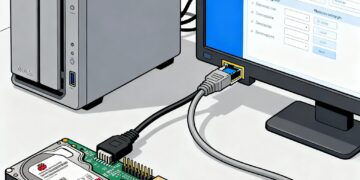
Tools > Board > Arduino AVR Boardsand select Arduino Mega or Mega 2560. - Select Your Port: Connect your robot to your computer with a USB cable. Go to
Tools > Portand select the port that has your Arduino Mega listed next to it (e.g., COM3 on Windows or /dev/cu.usbmodemXXXX on Mac).
Your workshop is now ready.
Part 2: The “Hello, World!” of Robotics – Testing the Motors
Before we can do anything complex, we need to confirm that our wiring from Session 6 is correct and that we can command each motor to move. We’ll write a simple program to spin one motor forward, then backward.
In the Arduino world, we use three key functions to control our L298N motor drivers:
pinMode(pin, OUTPUT);: This tells the Arduino that a specific pin will be used to send signals out to a component.digitalWrite(pin, HIGH/LOW);: This sends a simple on or off signal. We’ll use this for the direction pins (IN1,IN2, etc.).analogWrite(pin, speed);: This sends a variable signal, known as Pulse Width Modulation (PWM), which the L298N interprets as speed. Thespeedvalue can range from 0 (stopped) to 255 (full speed).
Copy the following code into your Arduino IDE. This code is written for the Front-Left motor we wired up in the last session.
C++
// --- Pin Definitions for Front-Left Motor ---
#define ENA 2  // Speed control pin (must be a PWM pin)
#define IN1 22 // Direction pin 1
#define IN2 24 // Direction pin 2

void setup() {
  // Set all the motor control pins to outputs
  pinMode(ENA, OUTPUT);
  pinMode(IN1, OUTPUT);
  pinMode(IN2, OUTPUT);

  // Initialize Serial Monitor for debugging
  Serial.begin(9600);
  Serial.println("Motor Test: Front-Left");
}

void loop() {
  // --- Spin Forward at Half Speed ---
  Serial.println("Spinning forward...");
  digitalWrite(IN1, HIGH);
  digitalWrite(IN2, LOW);
  analogWrite(ENA, 128); // Speed from 0 (stop) to 255 (full)
  delay(2000); // Wait for 2 seconds

  // --- Stop ---
  Serial.println("Stopping...");
  digitalWrite(IN1, LOW);
  digitalWrite(IN2, LOW);
  delay(1000); // Wait for 1 second

  // --- Spin Backward at Half Speed ---
  Serial.println("Spinning backward...");
  digitalWrite(IN1, LOW);
  digitalWrite(IN2, HIGH);
  analogWrite(ENA, 128);
  delay(2000); // Wait for 2 seconds

  // --- Stop ---
  Serial.println("Stopping...");
  digitalWrite(IN1, LOW);
  digitalWrite(IN2, LOW);
  delay(1000); // Wait for 1 second
}
Upload this code to your robot. You should see the front-left wheel spin forward for two seconds, stop, then spin backward for two seconds.
Troubleshooting & Testing All Motors:
- If nothing happens: Double-check your wiring against the diagram in Session 6. Ensure your battery is charged and connected.
- If the motor spins in the wrong direction: The easiest fix is physical. Simply swap the two motor wires where they connect to the L298N’s output terminals.
- To test the other motors: Change the pin numbers at the top of the code to match the pins for the next motor (e.g., Front-Right uses ENA=4, IN1=30, IN2=32). Upload and test each wheel one by one until you’ve confirmed all four are working correctly.
Part 3: Giving Your Robot Senses – Reading the Encoders
A motor that just spins blindly is an open-loop system. To create our intelligent closed-loop controller, we need feedback. This is the job of the encoders.
An encoder sends out rapid pulses as the wheel turns. Trying to catch every single pulse in our main loop() is nearly impossible; the code would be too slow. Instead, we use a powerful feature of microcontrollers called interrupts. An interrupt forces the processor to pause whatever it’s doing, run a special piece of code (called an Interrupt Service Routine or ISR), and then resume its main task. This ensures we never miss a tick.
This code will read the encoder on the Front-Left wheel. The volatile keyword is important; it tells the compiler that this variable can change at any time (which it will, inside the interrupt).
C++
// --- Pin Definitions for Front-Left Encoder ---
#define ENCODER_A 21 // Must be an interrupt pin
#define ENCODER_B 20 // Must be an interrupt pin

// A 'volatile' variable can be changed by an interrupt
volatile long encoder_ticks = 0;

// Interrupt Service Routine (ISR)
// This function is called every time ENCODER_A changes state (rises or falls)
void readEncoder() {
  // Read the state of the other encoder pin to determine direction
  int b = digitalRead(ENCODER_B);
  if (b > 0) {
    // If B is high, we are spinning forward
    encoder_ticks++;
  } else {
    // If B is low, we are spinning backward
    encoder_ticks--;
  }
}

void setup() {
  // Initialize Serial Monitor
  Serial.begin(9600);
  Serial.println("Encoder Test: Front-Left");

  // Set encoder pins as inputs
  pinMode(ENCODER_A, INPUT);
  pinMode(ENCODER_B, INPUT);

  // Attach the interrupt to the ENCODER_A pin
  // The 'readEncoder' function will be called on every CHANGE of the pin's state
  attachInterrupt(digitalPinToInterrupt(ENCODER_A), readEncoder, CHANGE);
}

void loop() {
  // Print the current tick count to the Serial Monitor
  Serial.print("Ticks: ");
  Serial.println(encoder_ticks);

  delay(100); // Update 10 times per second
}
Upload this code. Now, open the Serial Monitor (Tools > Serial Monitor). When you manually spin the front-left wheel by hand, you should see the “Ticks” count go up when you spin it one way and down when you spin it the other. This confirms our robot now has a sense of its own motion!
What’s Next?
We’ve achieved two massive milestones today. We can command our motors, and we can sense their movement. We have successfully tested the two fundamental halves of a closed-loop system.
But “ticks” are not a very useful unit for control. To implement our PID controller, we need to know the wheel’s speed in a standard unit, like Revolutions Per Minute (RPM). In our next session, we will write the code to convert the raw tick count from our encoders into a real-time speed calculation. Once we know how fast our wheels are actually going, we’ll be just one step away from implementing the full PID brain.


Thank you for your sharing. I am worried that I lack creative ideas. It is your article that makes me full of hope. Thank you. But, I have a question, can you help me?